![]()
![]()
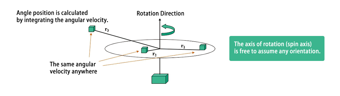
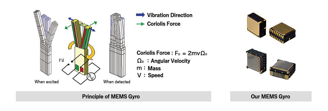
| Principle | When the angular velocity is applied to a mass with a speed, the Coriolis force occurs in the direction at a right angle to both speed direction and rotation axis. |
|---|
Our MEMS gyro vibrates the element in the shape of a tuning fork and detects the electricity produced by change of vibration mode by Coriolis force applied from rotational motion with the electrode which is placed on the sensor element.
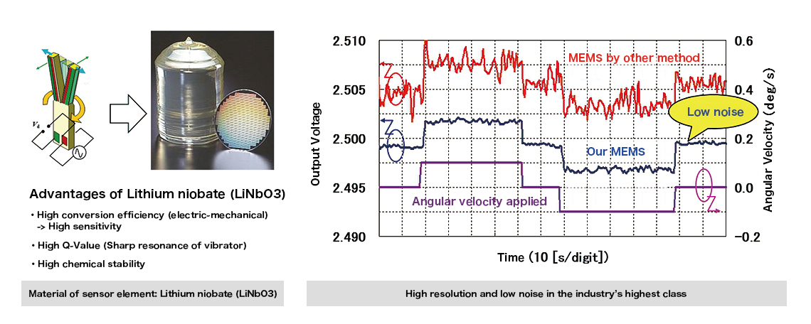
The material of our MEMS gyro sensor element is Lithium niobate
(LiNbO3).
Small size but high resolution and low noise in the industry’s highest class because of higher conversion
efficiency than other method
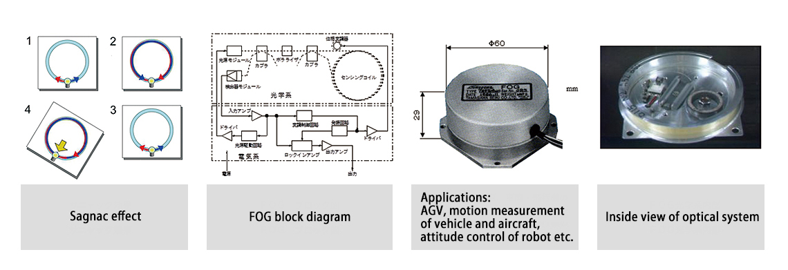
| Principle | A fiber optic gyroscope (FOG) detects the changes in orientation using the interference of light, which is created by two beams injected into the same fiber in opposite directions. The angular velocity is translated as the pattern of interference which is measured. |
|---|
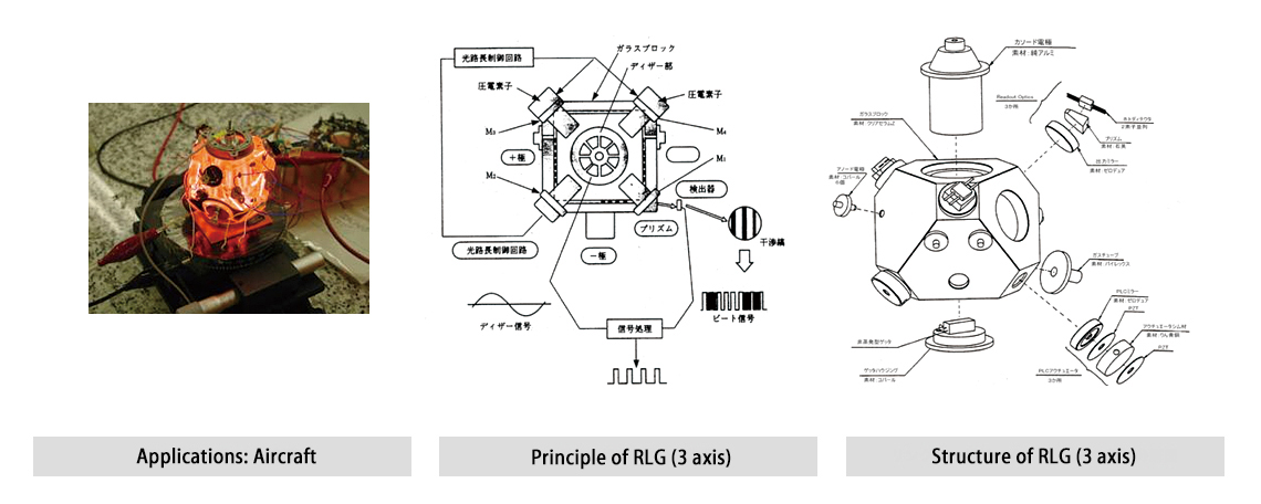
| Principle | A ring laser gyro (RLG) consists of a optical resonator, laser mirror & narrow glass tubule, where two laser beam are generated in CW and CCW by discharge of He-Ne. When the angular velocity is applied, a displacement of frequency of laser beam is made on a principle of Sagnac effect. A ring laser gyro (RLG) measures the displacement by counting a number of prismatic interference fringes. |
|---|
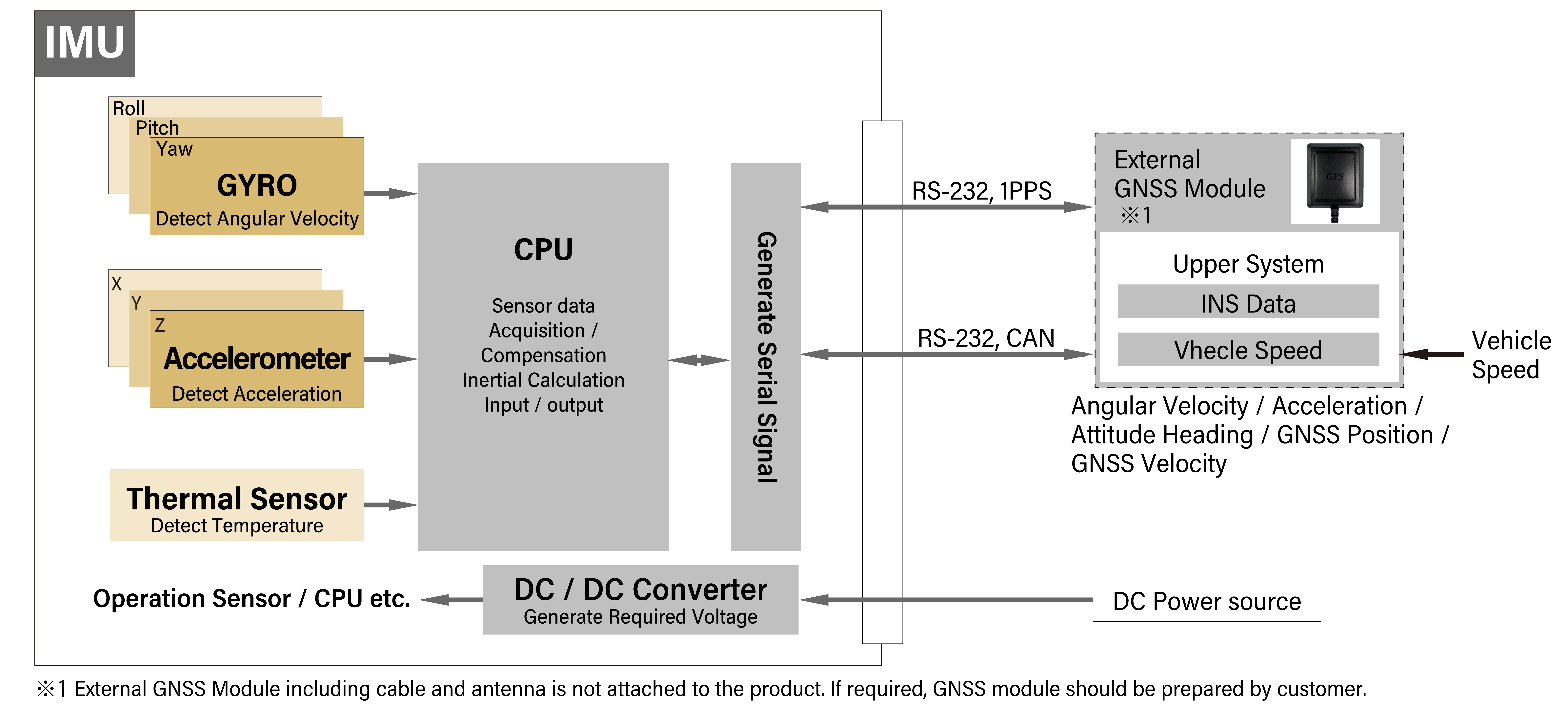
Our MEMS IMU not only detects and outputs 3-axis angular velocity and 3-axis acceleration but also calculates and outputs attitude angle (roll and pitch) and azimuth angle (yaw).
| Type | MEMS IMU | FOG & MEMS combined IMU |
|---|---|---|
| Exterior | 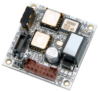 |
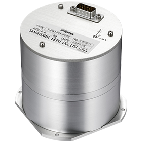 |
| Built-in sensor | MEMS Gyro(3 axes) MEMS Accelerometer |
MEMS Gyro(2 axes:Attitude) FOG(1 axis:Heading) MEMS Accelerometer |
| Features | Small and Lightweight | High Precision |
| Products page | MEMS IMU Products page |
FOG & MEMS combined IMU Products page |
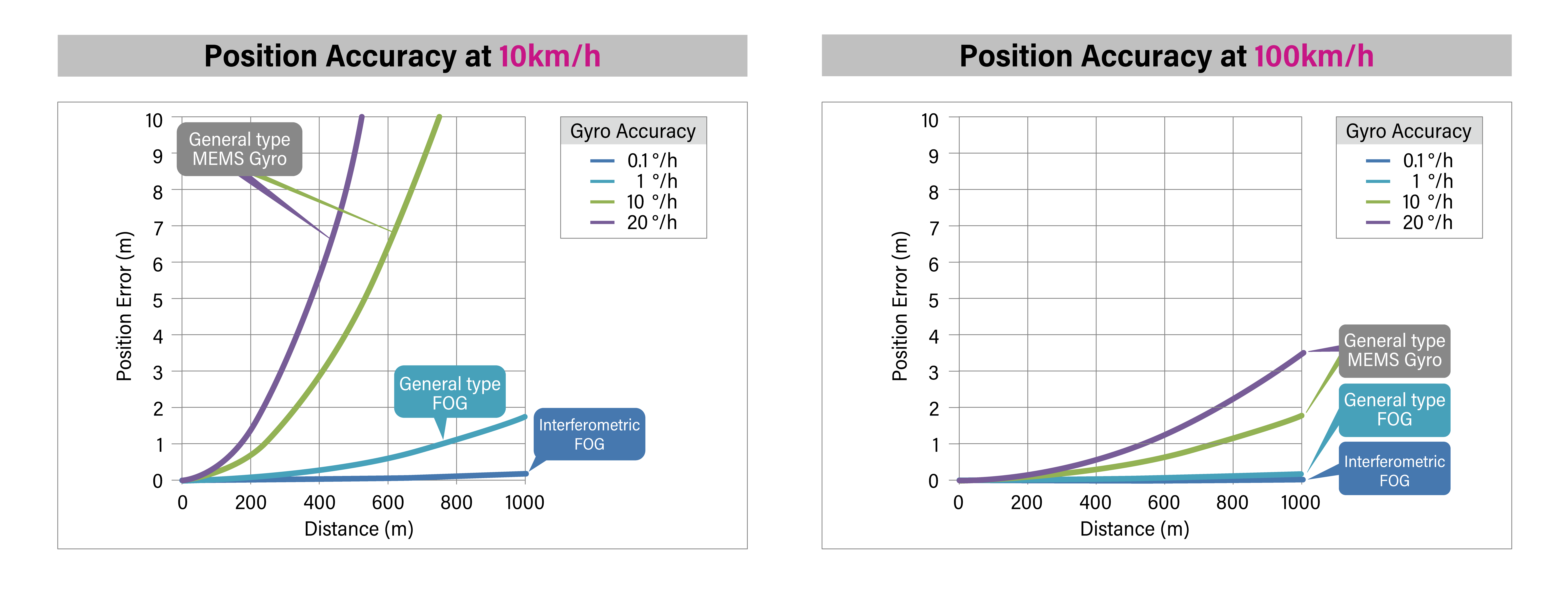
Through the use of GNSS with centimeter-level positioning accuracy, fully autonomous driving will come closer to realization.
However, the accuracy of localization is worsened in Tunnel or Multipath propagation. Gyroscope is used in those conditions.
In dead reckoning, position data is estimated by integral of gyroscope, odometer and accelerometer. Depending on the accuracy of gyroscope, errors of heading is accumulated. Therefore, high accuracy gyroscope is needed for dead reckoning.
Our MEMS IMU has two types of calculation methods, leveling calculation and GNSS/INS/VS, and we propose the most suitable calculation method for each application.
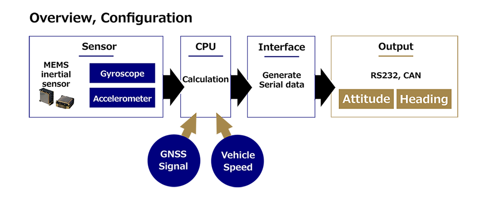
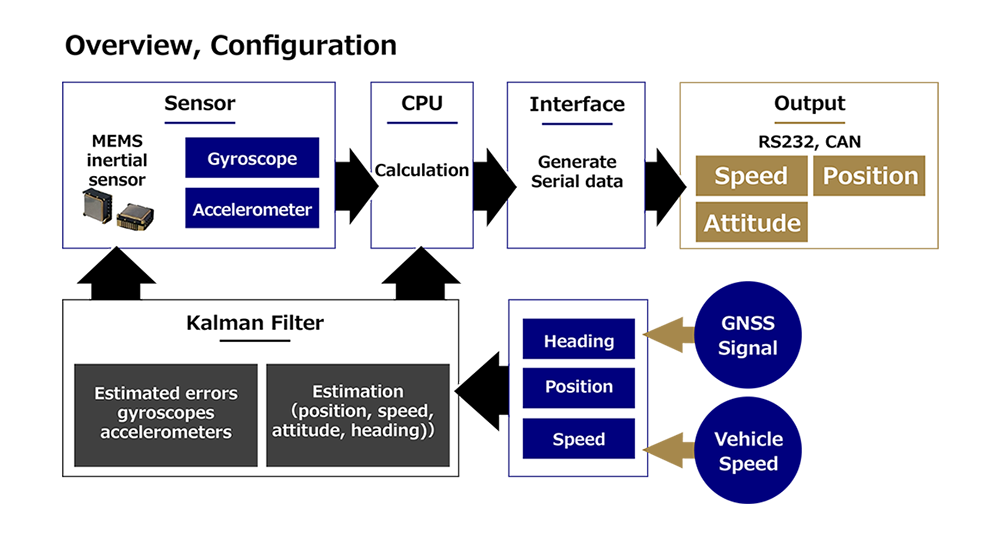
|
Please download the PDF of the leveling calculation and GNSS/INS/VS from here.
|
Since World War II, there had been a lot of studies of Gyroscope under the concept of high accuracy, compact-size and light weight for the need of aircraft or missile. In those days, Attitude Gyro and Rate Gyro were the standard types of Gyroscope and often used for aircraft, missile or rocket, etc.
Until the late 70’s, Mechanical Gyroscope was commonplace. For high-end products such as aircraft navigation system, Stable Platform Gyroscope which consists of Multi-gimbal was often used. The characteristics of Stable Platform Gyroscope is high accuracy and narrow range of angular velocity. This type of Gyroscope was called Platform Gyroscope. In 1970’s, Strapdown Gyroscope was also introduced to market. The word “Strapdown” is used in contradistinction to “Platform”, which means that detection range is wide, and attitude angle is calculated by 3 axis of angular velocity. This technology is realized by developed computer technology.
In 1980’s, Inertial Navigation System by Strapdown Ring Laser Gyro was adopted by Boeing and Airbus. In those
days, Strapdown Gyroscope was gradually increased while Platform Gyroscope was decreasing.
From 1980’s to 2000, mechanical Gyroscope was replaced by non-mechanical Gyroscope. For example, Ring Laser
Gyroscope was in practical use in 1980’s, and Fiber Optic Gyroscope followed in 1990’s.
In 1970’s, Hydrodynamic Gyroscope such as Gas Rate Gyro and Vibrating Gyroscope was actively developed in US.
The accuracy of these Gyroscopes is not very high, but they are superior in operating life, environmental
performance and cost. Therefore, a lot of Japanese manufacturers were interested in and focused on these
Gyroscopes. Since then, Hydrodynamic Gyroscope or Vibrating Gyroscope were used for mass-produced automobile or
camera and changed its image of expensiveness or short operating device. Honda, a Japanese automaker, paid an
attention on Hydrodynamic Gyroscope (Gas Rate Sensor) which was initially developed for Japanese Defense
program. Honda succeeded in developing low-cost & high performance Hydrodynamic Gyroscope and used them for car
navigation system in early 1980’s. This achievement made an impact on Japanese industry as Gyroscope was used
for general industry for the first time.
Since then, a lot of Japanese manufacturers have focused on Vibrating Gyroscope or Fiber Optic Gyroscope. This trend would affect the development of MEMS Gyroscope later. It is considered that MEMS Gyroscope will become more common from now on. Gyroscope is facing with conversion from Military based development to Industry standard.
2020
Developed the new-concept MULTI SENSOR, combining an i-FOG with 0.1°/h heading accuracy and our MEMS IMU boasting 0.1°attitude angle precision, for autonomous driving and automated large scale construction machinery widely adopted by customers.
2023
Launched the fourth-generation TAG310 series with compact, low-cost, and environmentally rugged MEMS IMUs designed for industrial vehicles and work robots, targeting ICT, EV, and IoT integration.
2025
With revamped internal sensors, the fifth-generation MEMS IMU TAG320 has been released in two versions: a cost-effective “Standard Model” and an ultra-precise “High-Precision Model.”
